OSIP Backplane

General Info
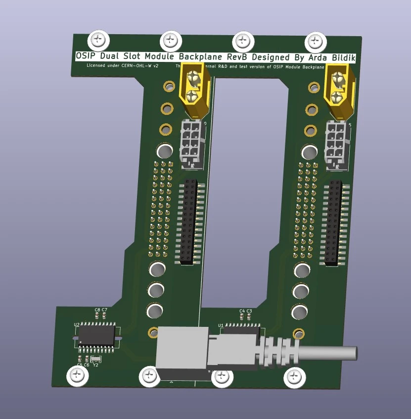
OSIP Backplane enables power and data connectivity between the OSIP Main System and the 2x instrument modules while keeping electrical isolation between every system connected to the backplane. Modules communicate over USB for ease of use and software compatibility. Backplane provides airflow paths for cooling any high power modules that will be developed such as PSU4010A and EL8020 modules currently under development.
Connectivity
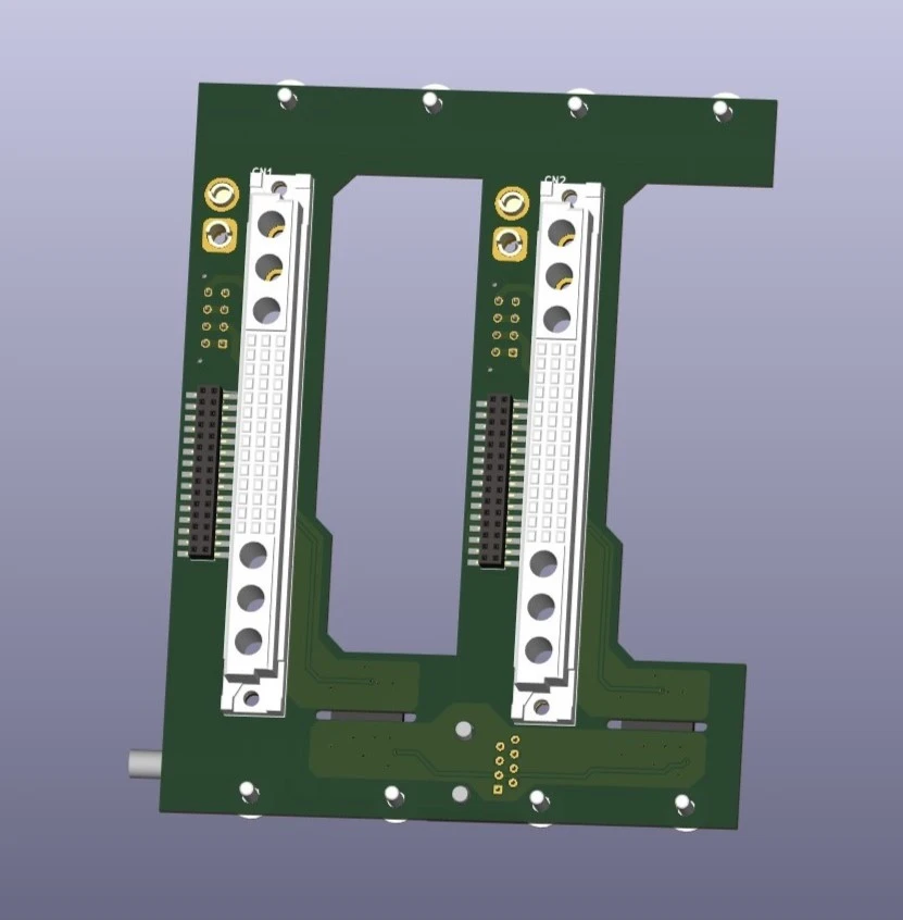
Backplane uses DIN41612 compatible Type M 42+6 Pin Eurocard Connectors. 42 pins in the middle
of the connector is used for connecting data/control interfaces and ±12V, +5V power rails.
There are also 6 modular connector slots which can be configured with different connectors such as 40A
power, 50/70ohm coax, HV plug-in connectors etc.
Latest pinout diagram for current RevB Backplane can be seen in the table below.
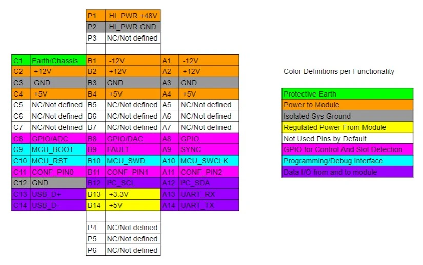
Pinout definition for Type M Connector Used in the Backplane
Isolated USB connections for interfacing with the modules from the internal/external controller computer
will be carried over a RJ45 terminated CAT-5e cable which is commonly available and can be easily. A single
CAT-5e cable carries 2x USB 2.0 signals and power for the ADuM4165 isolators.
Data and Control
By default 480Mbps USB2.0 is used for main
data stream is isolated by ADuM4165 isolators from Analog Devices. For additional uses and internal
connections SWD,I2C and UART interfaces are available alongside 5 GPIO pins
(2 of which could also have ADC and DAC capabilities) For any custom interfaces the user might want
to implement in a custom module there is 9 available connections in the connector.