OSIP PSU4010A 40V 10A 400W Lab PSU

Important! This design is still under development and design is open to changes. Currently RevB is the latest version of this design in the Eurocard format as of now.
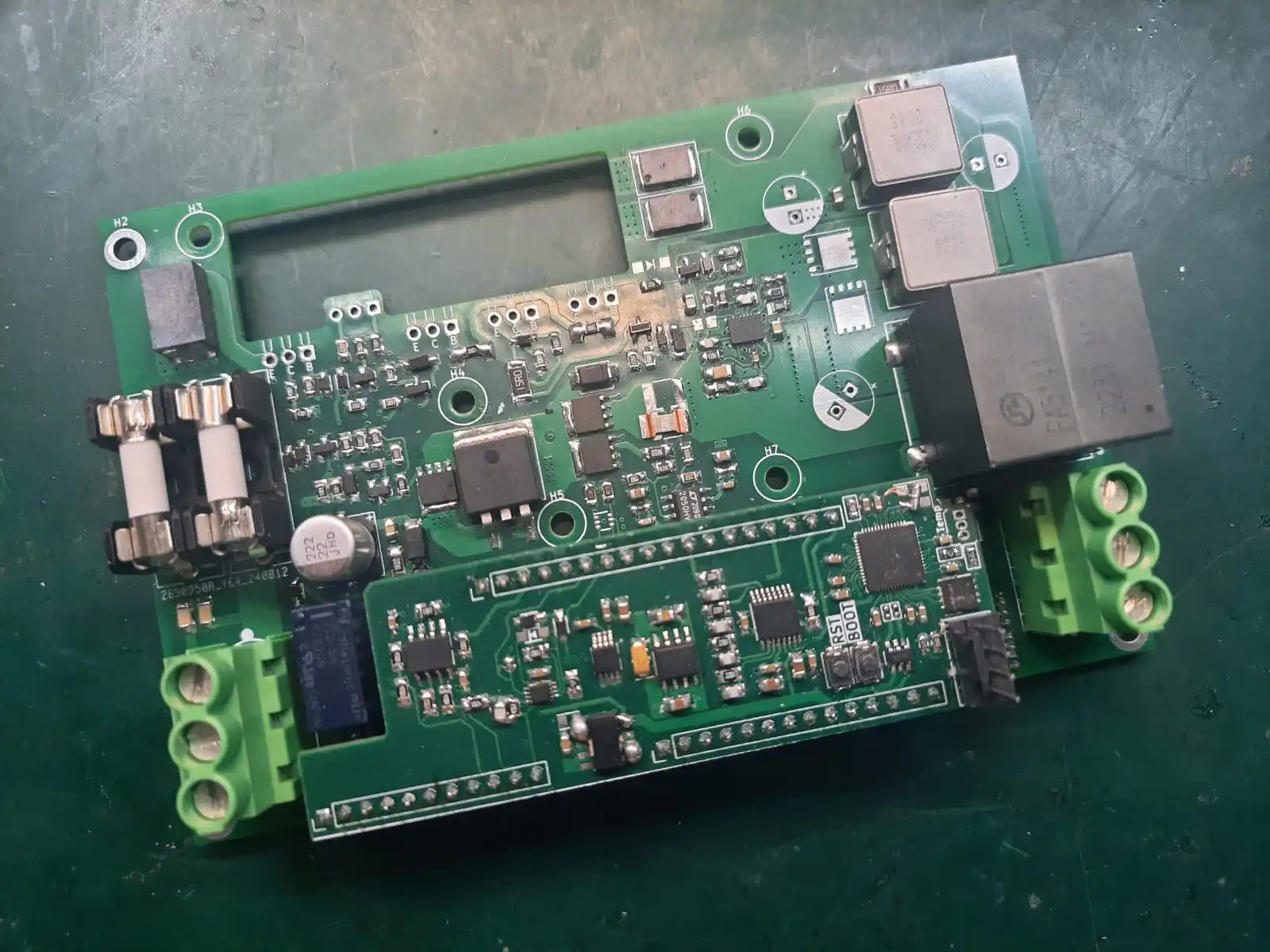
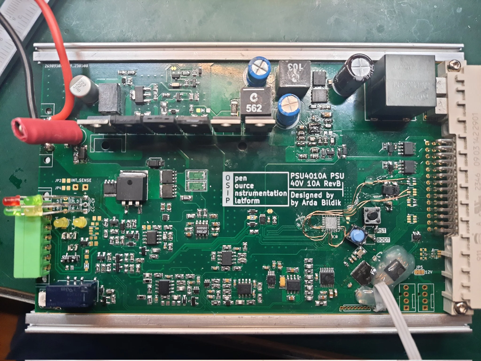 Left: PSU4010A RevA Module Right: PSU4010A RevB Module
General Info
PSU4010A is a modded and upgraded version of DCP405 from Envox.
PSU4010A RevB is a re-designed power module in the form factor of an Eurocard Module so it can be used plug-n-play with the OSIP Chassis.
It can provide continuous 400W 40V 10A output with hybrid pre-buck and post-linear regulation stages. Table below shows
differences between PSU4010A and DCP405.
| PSU4010A RevA | PSU4010A RevB | DCP405 | |
| PCB Size (mm) | 85mm x 130mm | 100mm x 160mm | 95mm x 185mm |
| Output | 40V-10A 400W | 40V-10A 400W | 40V-5A 200W |
| Vout Range | 40V-0V or 10V-0V | 40V-0V only | 40V-0V only |
| Iout Range | 10A-0A or 50mA-0mA | 10A-0A or 100mA-0mA | 5A-0A or 50mA-0mA |
| Control I/O Isolation | User Provided | User Provided | On-board |
| MCU | RP2040 | RP2040 | No on-board MCU (included in BB3) |
Every other specification is mostly same between PSU4010A and DCP405 since the PSU4010A is based of off DCP405.
You can access the original github repository by Envox/EEZ-open containing the design files of DCP405 from here.
!!Disclaimer!! As of now the firmware is not in the final stage and is messy as it can be with broken, test functions etc. Due to the logistics problems I have not been able to acquire required MCP23017 I/O expander and firmware is written to work with bodged connections.
Current hardware design files, latest firmware, computer software and documentation will be published after full evaluation of the system
Output Calibration
Output calibration is seperated into 2 sections for Voltage and Current calibration.
– Voltage Calibration –
After entering calibration by sending “VCAL\n” through serial, you can cancel the calibration and use the old calibration as is by sending “CANCEL\n” anytime.
Step-1: Program notifies calibration start to user and waits for user to confirm that a voltmeter is connected to the output by the confirmation message “OK\n”
Step-2: Program sets output to low-end reference point (< 5V) for 5 seconds and waits for user to enter read measurement from voltmeter in the form of as example “2.1234V\n”
Step-3: Program sets output to high-end reference point (> 35V) for 5 seconds and waits for user to enter read measurement from voltmeter in the form of as example “38.1234V\n”
Step-4: Program asks the user if the new calibration should be saved to the memory. Calibration is saved with “OK\n” and gets discarded with “CANCEL\n” command.
– Current Calibration –
After entering calibration by sending “ACAL\n” through serial, you can cancel the calibration and use the old calibration as is by sending “CANCEL\n” anytime.
Step-1: Program asks user for which current range calibration to enter. 10A range is selected by sending command “HI\n” or 100mA range can be selected by sending command “LO\n”
Step-2: Program notifies calibration start to user and waits for user to confirm that an ampmeter is connected to the output by the confirmation message “OK\n”
Step-3: Program sets output to high-end reference point (> 8A or > 80mA) for 2 seconds and waits for user to enter read measurement from ampmeter in the form of as example “8.1234A\n” or “80.1234mA\n”
Step-4: Program notifies user on possible current measurement range change on ampmeter and waits for user to confirm that an ampmeter is connected to the output in right range by the confirmation message “OK\n”
Step-5: Program sets output to low-end reference point (< 1A or < 10mA) for 2 seconds and waits for user to enter read measurement from ampmeter in the form of as example “0.8123A\n” or “8.1234mA\n”
Step-6: Program asks the user if the new calibration should be saved to the memory. Calibration is saved with “OK\n” and gets discarded with “CANCEL\n” command.
PSU4010A Control Software & SCPI Control Commands
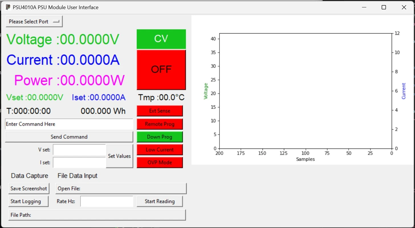
Comms are still at test version and more extensive functions/capabilities will be added on the final version.
Data transfer made over USB at 1kHz output rate that will be user configurable. Final version will also have
standart SCPI compatible control commands implemented for drop-in replacements.
As of now for 1kHz data rate a lightweight command structure is used between the module and python program. SCPI commands are semi-implemented for basic functionality.