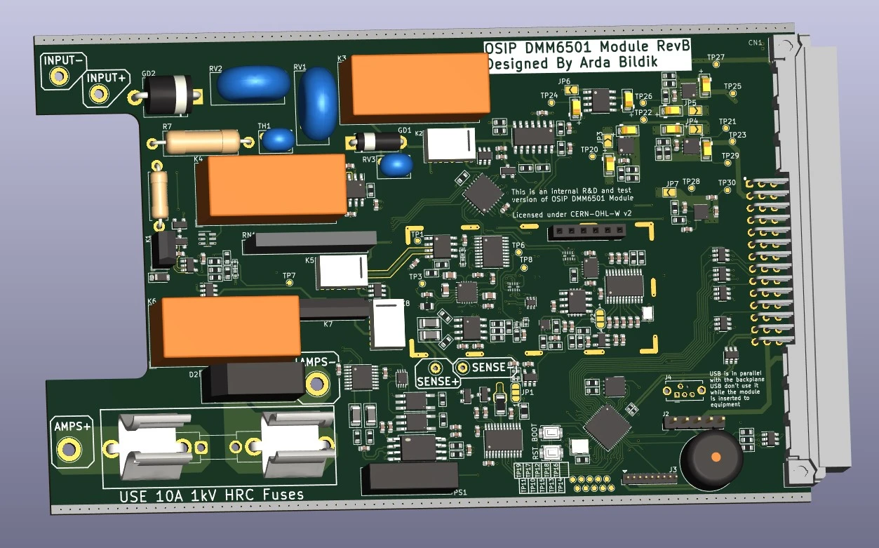
DMM6501 6.5 Digit Multimeter

Important! This design is still under development and design is open to changes. Currently RevB is the latest version and it has not been prototyped or tested in any way.
General Info
DMM6501 is a 6.5 digit DMM Module custom designed by Arda Bildik. Module has capabilities to measure voltages
upto 1000V DC and 750V AC, currents upto 20A DC and 15V AC, resistances upto 2GΩ with 2W and 4W measurements
and has the capability of measuring voltage and current at the same time for power measurements. DMM6501 also
provides inductance and capacitance measurements although these are fully EXPERIMENTAL functions and has NOT
been tested in the slightest bit.
Important Notice!
True RMS can be used with voltage or current measurements based on user selection. But it cant be used with
both measurements at the same time. Because of this design choice RMS power measurements might not be as
precise as stated in here.
| MCU | RP2040 |
| ADC Converter | 24bit AD7172-2 |
| Current Source DAC | 16bit AD5420 |
| Voltage Reference | REF5025 |
| True RMS Converter | AD8436 |
Input Protection
DMM6501 is designed to measure 1KV between its positive and negative input terminals and it can handle 5KV-10KV on
its input with no problems. Input protection is done through MOVs, PTCs and GDTs for fast and redundant protection
of the input terminals.
Sense input is protected through fusable current limiting resistors, clamping diodes and an analog buffer that is
able to handle high common voltages on its inputs to handle voltages much higher and lower compared to the input
negative terminal while still enabling it to perform its measurements.
Current measurement is totally isolated from the rest of the DMM6501 enabling it to make high-side or low-side
current measurements. Shunts and other sensitive circuitry is protected by high current clamping diodes and a
HV or HRC fuse depending on the use case of the DMM6501.
Isolation provided between the modules and with reference to the earth/ground enables the DMM6501 to function as a
floating non ground/earth referenced multimeter. This provides it with 2KV max. handling capacity between any
terminal and ground/earth.
Input and Sense Measurements
DMM6501 uses its input terminals to internally measure voltage over test leads and the DUT for 2W probing
mode. Sense terminals are used for measuring voltages directly on the DUT with 4W Kelvin probing mode.
DMM6501 automatically disables internal sensing through input terminals when device is set for measuring
voltages to protect the internal circuitry from high voltages. Based on the measurement mode a digital
controlled PGA can be used to increase measurement accuracy on the input/sense terminals.
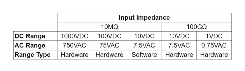
Voltage Measurements
DMM6501 has a high impedance 100GΩ (10V max.) and a 10MΩ (1KV max.) modes for voltage measurements. 100GΩ
range can be used to measure high impedance analog signals such as opamp inputs, buffer inputs etc. 10MΩ
is used for general purpose and high voltage measurements upto 1000V DC and 750V AC voltages. All available
ranges can be seen in the table below.
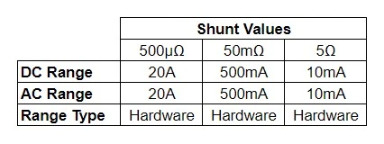
Current Measurements
DMM6501 has 3 current ranges for high current measurements, generic measurements and low current measurements
with 50mV max. shunt burden voltage. Physical mechanical relays are used for all ranges to ensure low leakage
for low current measurements. Current measurement section is fully isolated from rest of the device to allow
user to make either high-side or low side current measurements while measuring voltage at the same time.
Enabling power measurements up to 2kW on the max. ratings that DMM6501 can handle.
Resistance Measurements
DMM6501 has a digitally controlled AD5420 16-bit current DAC output of which can be set between 0-20mA for lower or
higher current resistance measurements. Based on which mode resistance is measured. If 2W mode is used sensing is
done through input terminals for 4W Kelvin mode sensing is done through the external sense terminals.
Experimental Capacitance and Inductance Measurements
DMM6501 RevB has an experimental capacitance and inductance measurement circuitry for basic testing of
components. Capacitance measurement uses the constant current source provided by the AD5420 16-bit current
DAC and a trigger circuitry to measure charge and discharge time of the capacitor and calculate the capacitance of it.
Inductance measurement uses a parallel known value capacitor to form a LC circuit with the DUT inductor and a
mosfet switch to create a pulse for to the LC circuit. Trigger circuitry then measures and calculates the
resonant frequency of the LC circuit and calculates the inductance.